What Is CNC CAD/CAM Software? A Beginner’s Guide
How CNC CAD/CAM software turns a drawing into G-code: design, toolpath generation, simulation and post-processing, followed through one real project from sketch to file.

A CNC router can’t read a drawing. It reads G-code: a long list of coordinates and speeds that says, line by line, where the cutter goes next. Somewhere between the shape in your head and that list, something has to decide which bit to use, how deep to cut, which way to go round each line and what to do about the part coming loose at the end.
That something is CNC CAD/CAM software. CAD is where you design the part. CAM is where you plan how the machine will cut it. A post-processor then writes the plan as G-code your machine understands.
This guide walks through each step by following one small project from a sketch to a file you could run tonight: a 12 × 5 inch key rack with a mountain range pocketed into the front, five holes for hooks, and a cut-out around the outside.
What is CNC CAD/CAM software?
CNC CAD/CAM software is the program you use to design a part (CAD) and turn that design into toolpaths and G-code a CNC machine can run (CAM). It sits between your idea and the machine. Everything the router does, it does because a line in a file told it to, and the CAD/CAM software wrote that file.
- CAD (computer-aided design) is the drawing: the outline of a part, the letters on a sign, the holes in a bracket. For most router work it’s 2D vector geometry.
- CAM (computer-aided manufacturing) is the plan for cutting it: which cutter, how deep, how fast, in what order, and with what to hold the part in place.
- Post-processing is the translation step at the end of CAM. It writes the plan as G-code in the exact dialect of your controller.
Most router programs do all three in one window. That’s why people say “CAD/CAM” as one word. The one job they usually leave out is running the file on the machine, which belongs to a separate program called a sender.
The CNC workflow, start to finish
Every job, from a coaster to a cabinet, goes through the same six steps:
Let’s take the key rack through each one.
Step 1: Design the part (CAD)
Design is drawing what you want to make. For a router, that almost always means 2D vectors: lines, arcs and curves with exact dimensions, not pixels. You can draw them in the CAD/CAM program itself, or draw them somewhere else and import an SVG or DXF.
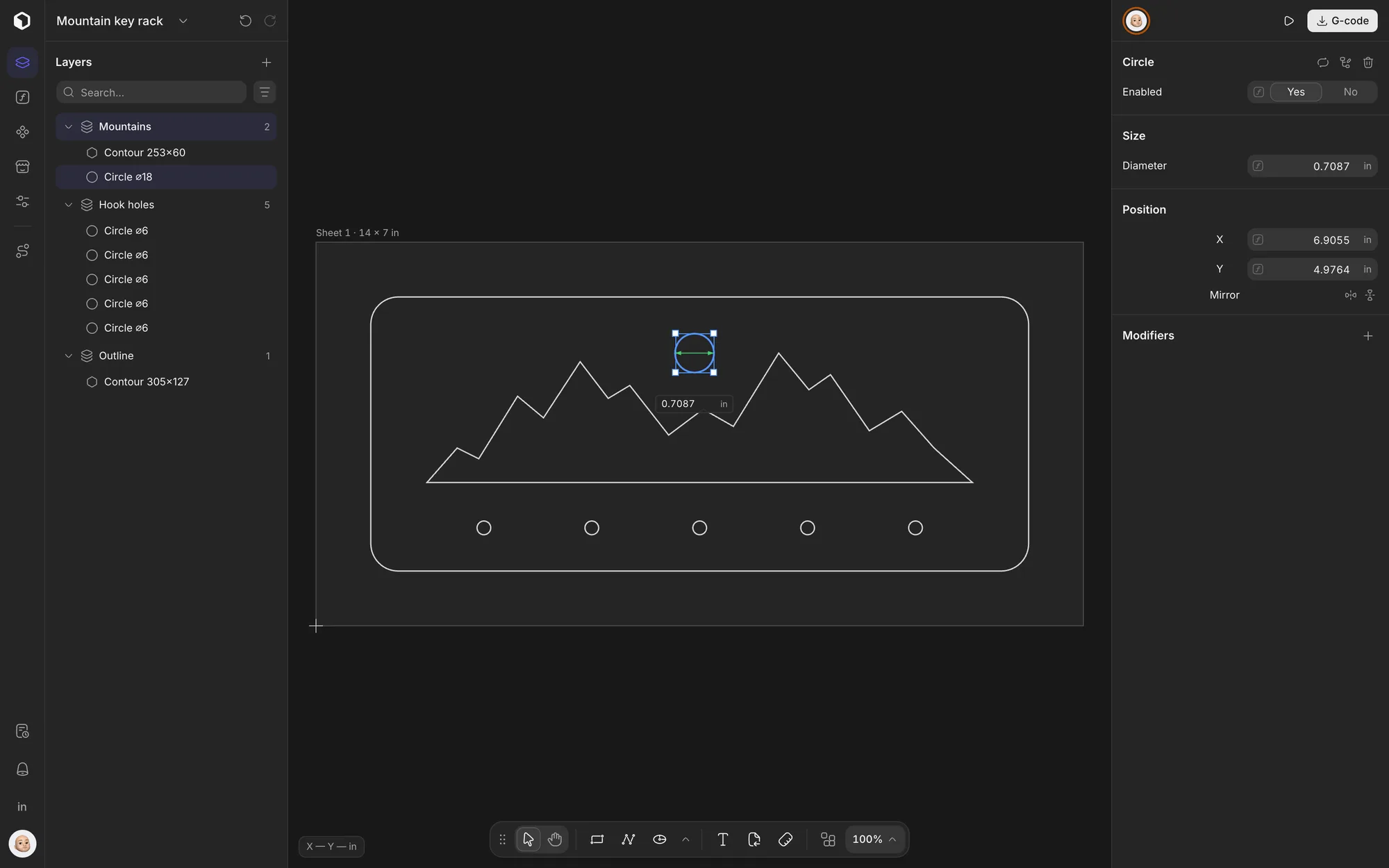
The key rack started as an SVG with three layers, one for each kind of cut: the mountain ridge and sun, the hook holes, and the outline of the board. Upcut kept those layers when I imported it, and that matters later, because operations attach to layers.
A few habits at this stage save hours later:
- Close your shapes. A pocket or a cut-out needs a closed outline. A gap of a hundredth of an inch between two lines that look joined is the most common reason a toolpath refuses to generate.
- Check the units on import. A 12 inch board that arrives as 12 mm is easy to spot. One that arrives at 96% of its size, because two programs disagree about pixels per inch, is not. Measure something you know.
- Organise by how it will be cut. Put everything that gets the same treatment on the same layer: all the pockets, all the holes, all the cut-outs. Selecting toolpath targets becomes one click.
- Design for the cutter. A round bit can’t cut a sharp inside corner. The smallest inside radius you can get is the radius of the bit.
Some programs, Upcut and Fusion among them, also let you design parametrically: a part’s dimensions are named values, so changing the width of a cabinet resizes every panel that depends on it. You don’t need that for a key rack. For anything made in several sizes, it’s the difference between editing one number and redrawing the job.
Step 2: Set up the job
Before any toolpath means anything, the software needs to know what it’s cutting and where. This is the least exciting step and the one behind most ruined first cuts.
- Stock. The width, height and, above all, the thickness of the material. Measure it with calipers. A sheet of “3/4 inch” plywood is often closer to 0.7 in, and a cut-out programmed for 0.75 in will go into your spoilboard.
- Machine. Its work area, its controller and its post-processor. The key rack is set up for a Shapeoko 5 Pro.
- Zero. Where X0 Y0 Z0 is. The two usual choices for Z are the top of the material and the machine bed. Whichever you pick here, you have to touch off the same place on the machine. The key rack uses the bottom-left corner and the material top.
Step 3: Generate toolpaths (CAM)
A toolpath is the line the center of the cutter follows. You don’t draw it. You pick an operation, point it at some geometry, choose a cutter and depths, and the CAM software works out the path. Change the drawing and the toolpath can be recalculated from it, rather than redrawn.
Router work mostly comes down to four operations:
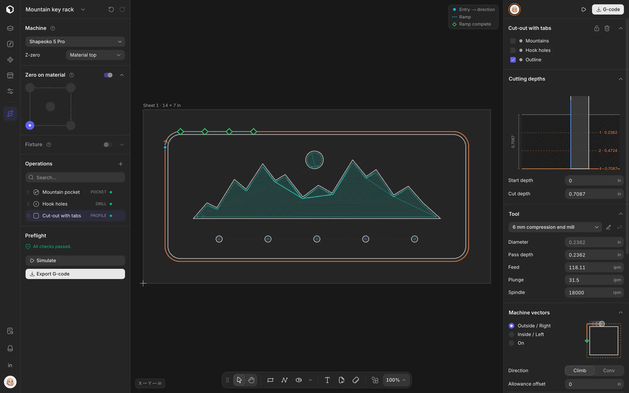
The key rack needs three of them:
- Mountain pocket clears the ridge and the sun 0.16 in deep with a 3 mm (about 1/8 in) flat end mill, in raster passes: back-and-forth lines, like mowing a lawn.
- Hook holes drills the five holes with the same bit, pecking down so the chips can clear.
- Cut-out with tabs profiles the outside of the board with a 6 mm compression bit, all the way through the sheet in three passes, ramping into each one rather than plunging. Four small tabs of material stay uncut, so the part doesn’t come loose and get caught by the bit on the last pass.
Cutters, feeds and speeds
Every operation needs a cutter and four numbers: spindle speed (rpm), feed rate (how fast the bit moves sideways), plunge rate (how fast it moves down) and pass depth (how much it takes per pass). Feed and speed are linked by chip load, the thickness of material each cutting edge removes per revolution:
feed rate = spindle rpm × number of flutes × chip loadCutter makers publish chip loads by material. Too small and the bit rubs and burns; too large and it chatters or breaks. Good CAM software starts you from sensible numbers for the tool and material, but treat them as starting points and listen to the cut.
Step 4: Simulate and check
A simulation plays the toolpaths back against a virtual block of material and shows you what will be left. It’s the cheapest place to make a mistake. In the simulation, a pocket that’s too deep or a cut-out on the wrong side of the line costs nothing. On the machine it costs a sheet of walnut.
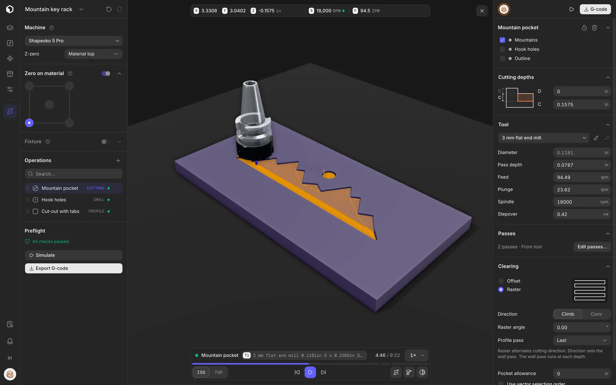
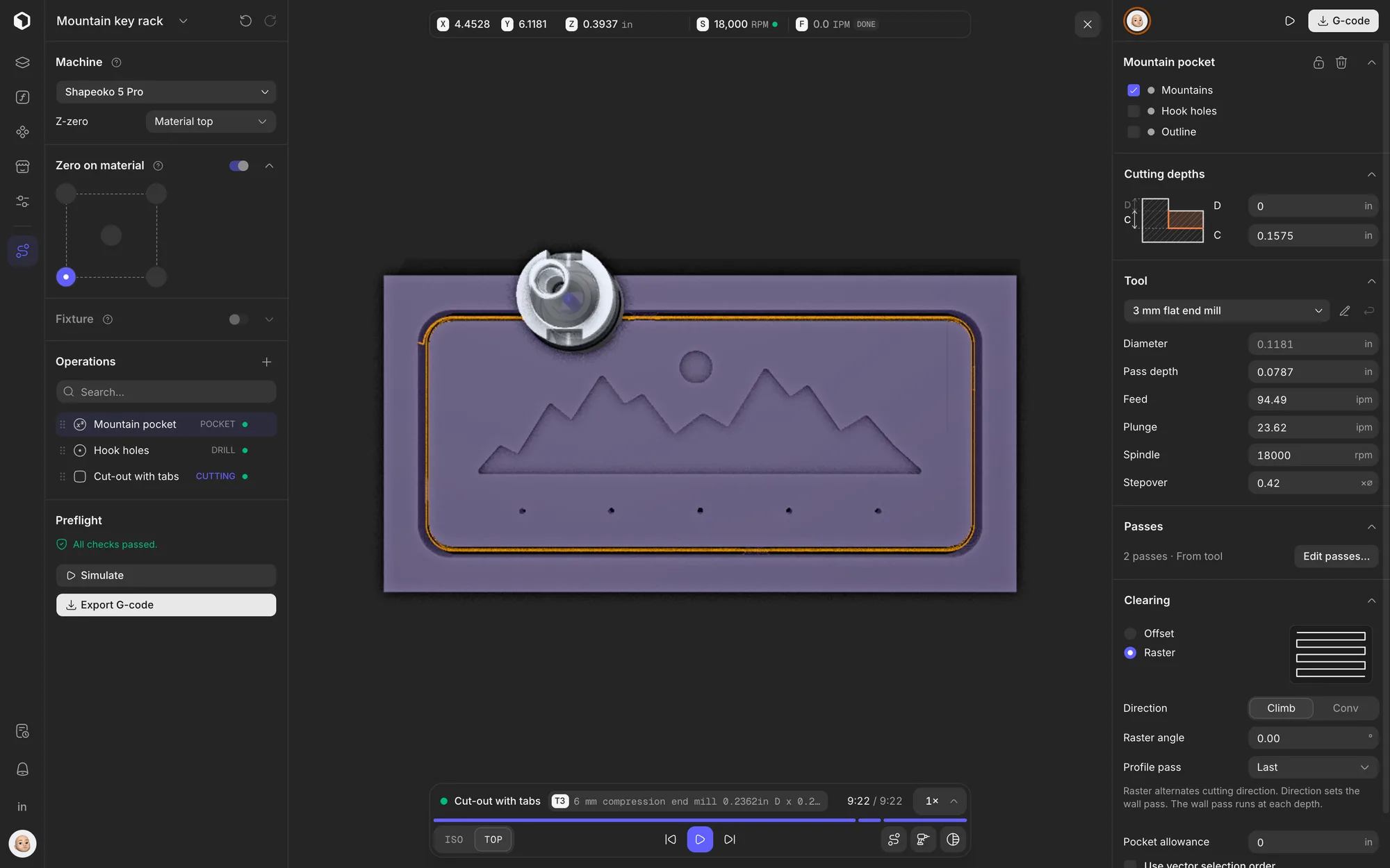
When you watch a simulation, look for:
- Cuts that go deeper than you meant, or through the bottom of the stock
- Material left behind in a pocket because the bit is too big for a corner
- A profile on the wrong side of the line, which makes the part a bit-width too small
- Rapid moves that travel low across the material or a clamp
Upcut also runs a preflight: a list of checks against your stock and machine that runs on every change. It warns about things worth a second look, like a drill that goes 0.47 in into whatever is under the stock. Problems the file shouldn’t leave with, like a job with nothing to cut or G-code that doesn’t match the toolpaths it was written from, block the export entirely. Other programs do some of this, some of it not at all. Whatever you use, don’t skip watching the cut.
Step 5: Post-processing: turning toolpaths into G-code
Toolpaths inside the CAM program are geometry. Your controller doesn’t want geometry; it wants G-code, and every controller wants a slightly different dialect. Inches or millimeters, how to start the spindle, whether it can change tools, how arcs are written, how many decimal places. The post-processor is the part of the CAM software that knows those rules for one machine and writes the file accordingly.
Here are the first lines of the key rack’s program, as written for the Shapeoko:
G54
T1
G17
G20
G90
G0Z0.7874
G0X0.0000Y0.0000
S18000M3
G0X6.7883Y4.7058Z0.3937
G1Z-0.0787F23.6
G1X7.0227F94.5G54uses the first work coordinate system, the zero you set on the machine.G17puts arcs in the XY plane.G20means inches andG90means absolute coordinates. Every number after this is measured in inches from zero.G0is a rapid move: as fast as the machine goes, used only in the air. Here it lifts to a safe height first, then moves to the start.S18000M3starts the spindle clockwise at 18,000 rpm.G1is a cutting move at the feed rateF: down 0.0787 in at 23.6 inches per minute, then across at 94.5.
Notice what isn’t there: there’s no tool-change command. A Shapeoko has no automatic tool changer, so the post splits the job into one file per cutter. You run the first, swap from the 3 mm bit to the 6 mm one, re-zero Z, and run the second. A router with a tool changer would get one file and an M6 between the two.
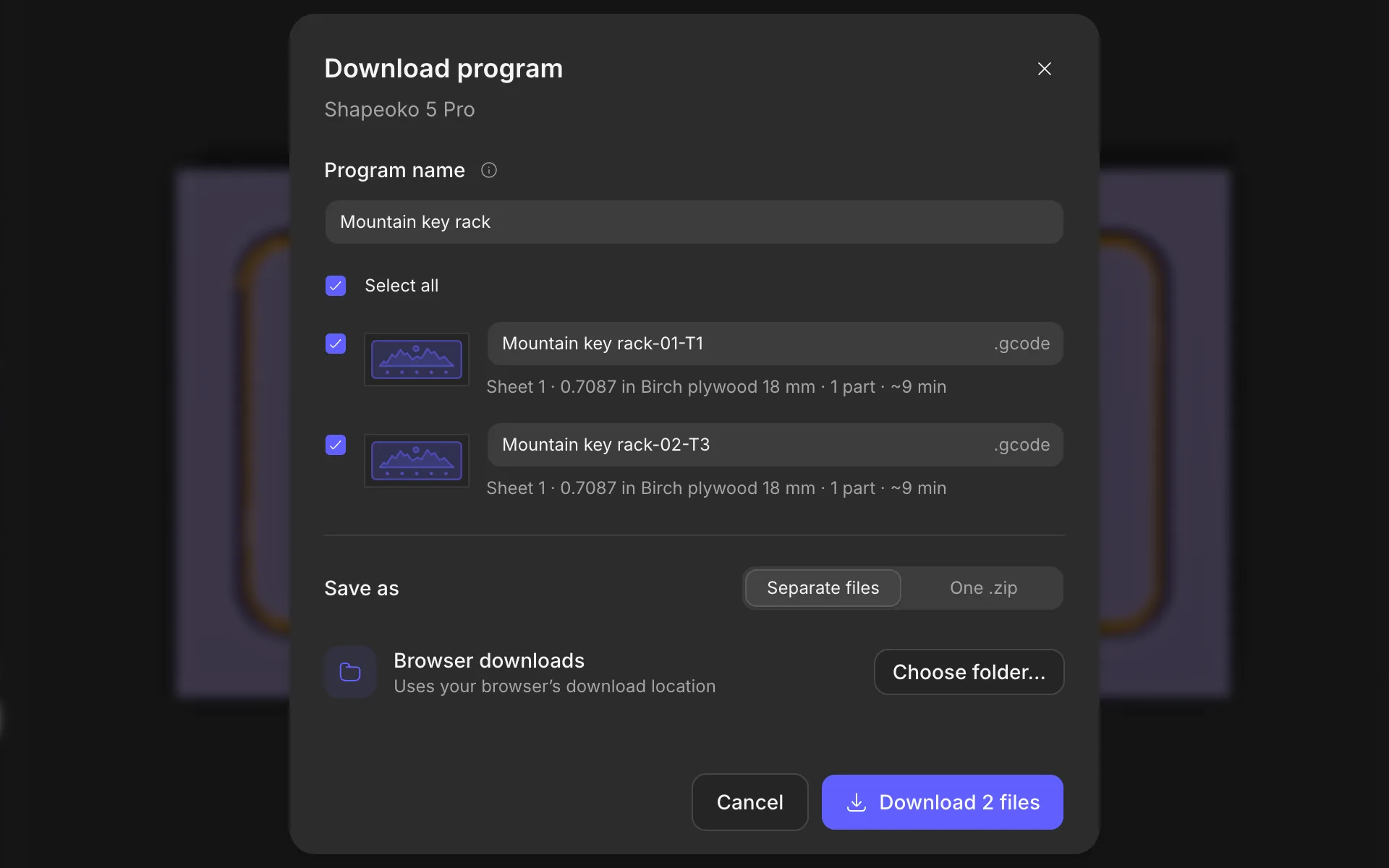
This is why the post-processor is the first thing to check when choosing software. The wrong one can write a file that runs without a single error and still moves the machine differently than the simulation showed. Pick the post for your exact controller, and run its first file with the spindle off and the bit well above the work.
Step 6: Send the file and cut
The last step happens outside CAD/CAM software, in a sender: gSender, Universal Gcode Sender, Carbide Motion, CNCjs, or your controller’s own software. Upcut stops at the file on purpose. You run it from the sender you already trust. Load the file, jog to the corner you chose as zero, touch off X, Y and Z, and start.
For a first run of any new program or post, do an air cut: set Z zero an inch above the material and run the whole file. If the machine traces the shape you saw in the simulation, in the place you expect, lower Z and cut for real.
All-in-one or separate programs?
You can do all of this in one program or spread it across several. Neither is wrong; it depends on what you make.
If you’re choosing, my guide to the best CNC router software compares nine of them by machine, price and the work they’re good at.
Common beginner mistakes
- Zero in the wrong place. Setting Z on the bed when the job expects the material top cuts a whole sheet-thickness too deep.
- Nominal thickness. Typing the thickness printed on the label instead of what the calipers say.
- Profiling on the line. Cutting along a part’s outline instead of outside it makes the part one bit-width smaller than you drew.
- No tabs. A part that comes free on the last pass can catch on the bit and get thrown or chewed.
- The wrong post. Inches read as millimeters, or a spindle command your controller ignores.
- Skipping the simulation. It takes a minute, and it’s where every mistake above is cheapest to find.
Frequently asked questions
What does CAD/CAM stand for?
CAD stands for computer-aided design: drawing the part. CAM stands for computer-aided manufacturing: planning how a machine will make it, which for a CNC router means choosing cutters, depths and feeds and turning them into toolpaths and G-code.
Do I need separate CAD and CAM programs for a CNC router?
Usually not. Most CNC router software, including Vectric VCarve, Carbide Create, Easel, Fusion and Upcut, combines design and toolpaths in one app. You still need a G-code sender to run the file on your machine, unless your software includes one.
What is the difference between CAM software and a G-code sender?
CAM software writes the G-code file: it decides where the cutter goes. A sender, such as gSender, Universal Gcode Sender, Carbide Motion or CNCjs, streams that file to the machine's controller and lets you jog, set zero and start the job. CAM plans the cut; the sender runs it.
What is a post-processor in CAD/CAM software?
A post-processor translates the CAM software's toolpaths into the G-code dialect your controller expects: units, how the spindle starts, how tools change, how numbers and arcs are written. Choose the post for your exact machine and controller, and dry-run the first file it writes.
Is there free CNC CAD/CAM software?
Yes. Carbide Create, Kiri:Moto and FreeCAD are free, Easel has a limited free tier, Fusion has a free non-commercial personal license, and Upcut has a free plan that includes toolpaths, simulation and G-code export.
Wrapping up
CNC CAD/CAM software does one job in a few stages: it turns a drawing into instructions a machine can follow. You design the part, tell the software what you’re cutting and where, choose how each shape gets cut, watch it happen on screen, and let the post-processor write G-code for your controller. Then a sender runs it.
Once you see the steps, every program on the market is a different arrangement of them. If you’d like to work through them in a browser, with an AI agent drafting alongside you while you keep every machining number, try Upcut. Whichever you use, simulate before you cut.